Home > Nature of light > The mysterious behavior of individual photons

The mysterious behavior of individual photons

The Mysterious Behavior of Individual Photons

In 1807, Thomas Young confirmed that light shows properties of a wave through his interference experiment.
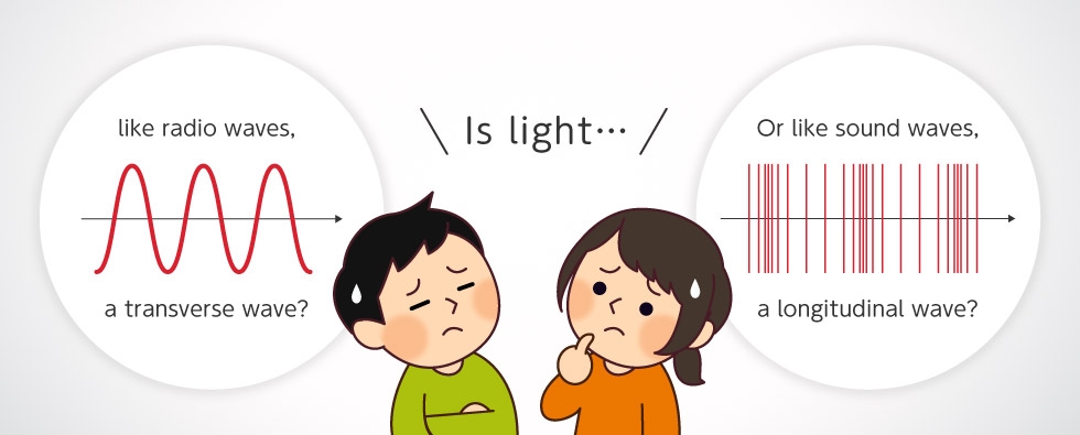
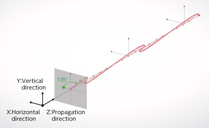
If light is a wave, then is it a “transverse wave” like a radio wave?
Or is it a “longitudinal wave” like sound?
Around the same time as Thomas Young, Augustin-Jean Fresnel and Domonique François Jean Arago found the answer to that question.
The concept of “polarized light”, which was known of since that time, was used in their experiment.
On this page we introduce their experiment using “polarized light”.

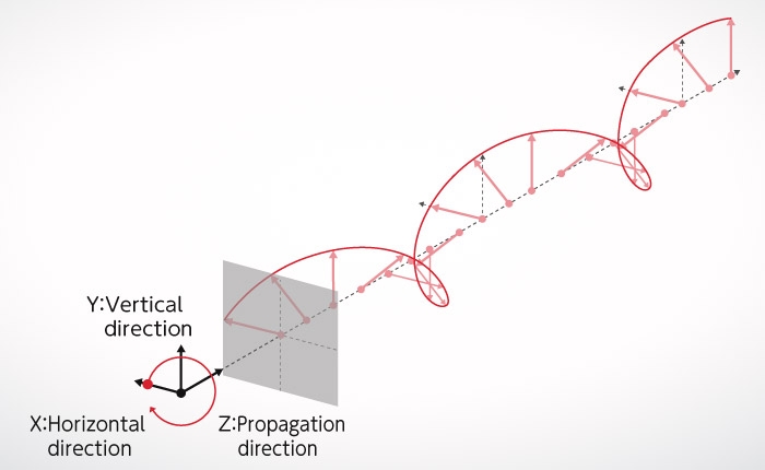
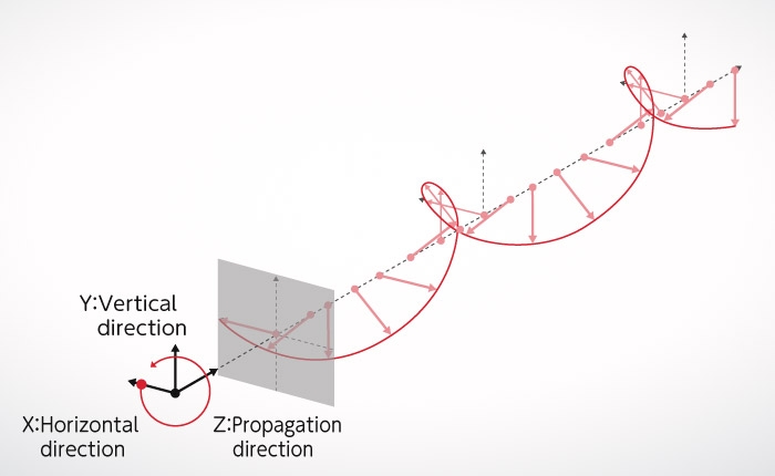
Light is a transverse wave

Sound is a “longitudinal wave” in which the rarefaction parts and compression parts oscillate in the direction of travel when propagating through the air, which is the medium for sound waves. Speakers generate sound by oscillating back and forth, so we can see that these are “longitudinal waves”.

Young's interference experiment, introduced in Wave-Particle Duality of Photons, can explain how interference fringes occur even if light is a “longitudinal wave”. Fresnel and Arago conducted interference experiments using the concept of “polarized light”, which was already known of at the time, and they proved that light is a “transverse wave”. This revealed another aspect of the true form of light.
Longitudinal wave? Or transverse wave?
Transverse wave? Or longitudinal wave?

Understand polarized light in diagrams

Before explaining what “polarized light” is, we must assume that light waves are “transverse waves” just like radio waves. Figure A-1 shows what happens when light travels in the Z direction and oscillates vertically (up and down) with respect to the ground. At this time, light is linearly polarized, in the vertical direction. Figure A-2 shows what happens when light oscillates horizontally, which is horizontal linearly polarized light. Figure A-3 shows vertical linearly polarized light and horizontal linearly polarized light traveling together. Because the two electric fields are combined as vectors, they are linearly polarized at a diagonal 45˚ angle to the left. In Figure A-4, the horizontally polarized waves appear inverted compared to Figure A-3. In this case, the slope of the combined wave is linearly polarized at a diagonal 45° angle to the right, unlike Figure A-3. Next, let’s look at Figure A-5. The phase of the vertical wave is 90° out of phase with Figure A-1. Here, the combined waves are spinning around. This is called circularly polarized light. Last, the waves in Figure A-6 are -90° out of phase with those in Figure A-1. In this case, while it is still the same circularly polarized light, the rotation direction is reversed. Therefore, even with two waves, horizontal and vertical, the plane of polarization changes significantly when combined through the phase relationship between the two waves. When light passes through the polarizer, it will become linearly polarized light with the same direction as the polarizer, regardless of what state the “transverse wave” was in at the time of incidence.
Figure A-1: Vertical linearly polarized light
Figure A-2: Horizontal linearly polarized light
Figure A-3: Linear polarization at an angle of 45° diagonally to the left
Figure A-4: Linear polarization at an angle of 45° diagonally to the right
Figure A-5: Circular polarization (light polarized clockwise to the right)
Figure A-6: Circular polarization (light polarized counterclockwise to the left)

Fresnel / Arago Experiment

Now that we have an understanding of polarized light, let's go back and reexamine the experiment conducted by Augustin-Jean Fresnel and Dominique François Jean Arago, who proved that light is a polarized "transverse wave".

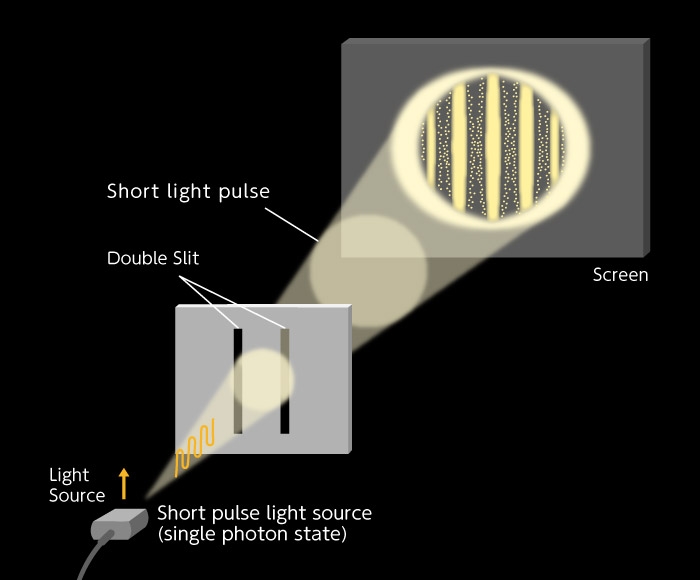
In Young's interference experiment with a single photon, which was introduced in Wave-Particle Duality of Photons, interference fringes showing the nature of waves appeared because of light transmitted through double slits. In this experiment, a single photon passed through both of the slits at the same time, despite the fact that it is thought to be just one particle, creating interference fringes that behaved like waves.

From these results, we can see that photons have the properties of both particles and waves, which is to say that they exhibit wave-particle duality.

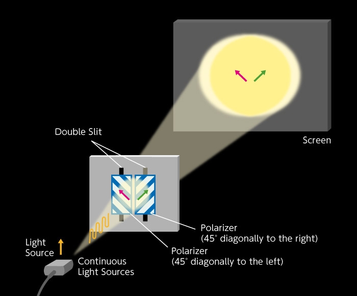
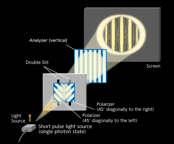
Next, look at the experimental set up of Fresnel and Arago in Figure B. Unlike Young's interference experiment, the double slits have a polarizer tilted 45° to the right and a polarizer tilted 45° to the left, respectively. For this reason, polarization of light, which is in fact “transverse waves” emerging from each slit, is an independent component positioned orthogonal to each other. The pink arrow and the green arrow in the figure indicate the directions of polarization. In Figure B-1, pink and green are orthogonal to each other. Here, no interference fringes appear on the screen (Figure B-1).
Reference: Nikkei Science March 2012 32 “Photon Paradox”

As a result, it is different from the results of Young's interference experiment, explained earlier in Wave-Particle Duality of Photons. It may be difficult to understand why interference fringes do not appear, but this will be explained later in another way.

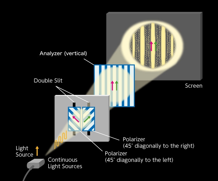
Next, as shown in Figure B-2, a vertical analyzer is placed behind the double slit (this is the same as a polarizer, but when several polarizers are placed on the same optical path, the last one is called analyzer). Now what happens? The polarization (oscillation direction) of light emitted from the right slit is tilted at a 45° angle to the right, but when it passes through the analyzer, the oscillation direction changes to vertical. Similarly, the polarization of light emitted from the left slit also has a vertical oscillation direction. There, both lights are polarized vertically on the final screen, so interference fringes appear because of interference (Figure B-2).
Figure B-1: No analyzer
Figure B-2: Vertical analyzer
Next, tilt the analyzer 45° to the right. Here, the “transverse wave” that passed through the left slit cannot pass through the analyzer, so the interference fringes do not appear because light is only coming from the right slit (Figure B-3). Conversely, when the analyzer is tilted 45° to the left, as in Figure B-4, no interference fringes will appear because light is only coming from the left slit.
Figure B-3: Analyzer is tilted diagonally 45° to the right
Figure B-4: Analyzer is tilted diagonally 45° to the left
Next, set the analyzer horizontally. Here, “transverse waves” that have passed through both slits have the same polarization. However, it should be noted that there are now arrows in the direction of the “transverse wave” of light. While horizontal polarization is the same, the direction of the arrow has reversed. This shows that the peaks and valleys of the “transverse waves” have been reversed. Bright and dark parts of interference fringes observed have now been reversed (Figure B-5). In Young's interference experiment, the center of the interference fringes does not turn dark. Conducting interference experiments with polarized light has shown that by comparing the brightness and darkness of interference fringes, one can clearly see light oscillates in a direction perpendicular to the direction of travel (and the fact that oscillation has a direction). Here it can be seen that one of the true forms of light is in fact a “transverse wave”.

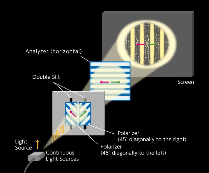
Finally, let's take look at Figure B-1, our first figure, and explain it in different terms. In this experiment, there is no analyzer. Following Figure B-2 and Figure B-5, we divide the two polarized “transverse waves” tilted 45° left and 45° right respectively, which passed through the double slits, so they are divided into four polarized lights; two vertically polarized lights and two horizontally polarized lights. The interference fringes that appear from the two vertically polarized lights as shown in Figure B-2 have bright centers. The interference fringes that appear the from two horizontally polarized lights as shown in Figure B-5 have dark centers. As such, the interference fringes have disappeared entirely as a result of overlap between the two interference fringes where bright and dark light have different positions. So, is it clear now?
Figure B-5: Analyzer is horizontal
Supplementary explanation of Figure B-1.
Figure B-6: Supplementary explanation of Figure B-1. Here we superimpose the screen when the analyzer is vertical (Figure B-2) and the screen when the analyzer is horizontal (Figure B-5). These two are in a state where the brightness and darkness of interference fringes are reversed, so that when they are overlapped, the dark part disappears and only the bright part appears. As a result, there are no interference fringes (Figure B-1).

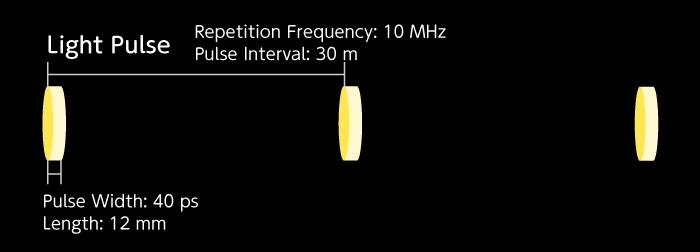
Individual photons of short light pulses

In “Young interference experiment with a single photon” introduced in Wave-Particle Duality of Photons, we produced a state where there is only one photon (single photon state) by dimming continuous lights such as halogen lamps. (Figure C-1). However, because originally photons are continuous light, even when the amount is reduced, there is still the chance that photons will be elongated and spread out spatially. In that case, even when darkened, there is risk that interference fringes will be formed by the two consecutive photons that come before and after. To solve this problem, Hamamatsu Photonics conducted an experiment using light pulses (Japanese Journal of Optics, 20 (1991) 108-111.). Although it is called a light pulse, this is in fact a short light pulse, lasting just 40 ps (picosecond = 1 trillionth of a second), and spanning just 12 mm. Because the pulse repetition frequency is 10 MHz, the pulse interval is 30 m. That is to say, 12 mm long photon pulses line up at intervals of 30 m, and these pulses do not overlap each other (Figure C-2). The light is gradually dimmed to create a short pulse single photon state with less than a single photon in the light pulse. This solves the problem mentioned earlier. Young’s interference experiment in this state shows the same results as in the state of continuous light. Even with short light pulses, one photon passes through two slits at the same time, thereby causing interference fringes. Here too, show the properties of both particles and waves simultaneously (Figure C-3, Video 1).
Figure C-1: Continuous light
Figure C-2: Short light pulse
Figure C-3: Young's interference experiment with short light pulses
Video 1:
Video 1: "Young's Interference Experiment with a Single Photon Using Short Light Pulses" (Hamamatsu Photonics, 1990)

Experiments conducted by Hamamatsu Photonics
(Fresnel / Arago polarization interference experiment in a short pulse single photon state)

Following this, a polarization interference experiment was done in a short pulse single photon state (Japanese Journal of Optics, 21 (1992) 165-168. Figure D). Here are shown 6 results, each with different polarization conditions. Specifically, E-1: without an analyzer, Figure E-2: analyzer in the vertical direction, Figure E-3: analyzer in the horizontal direction, Figure E-4: analyzer diagonally tilted 45° to the right, Figure E-5: analyzer tilted diagonally 45° to the left, and Figure E-6: incident light on the double slit is circularly polarized (the analyzer is the same as Figure E-2).

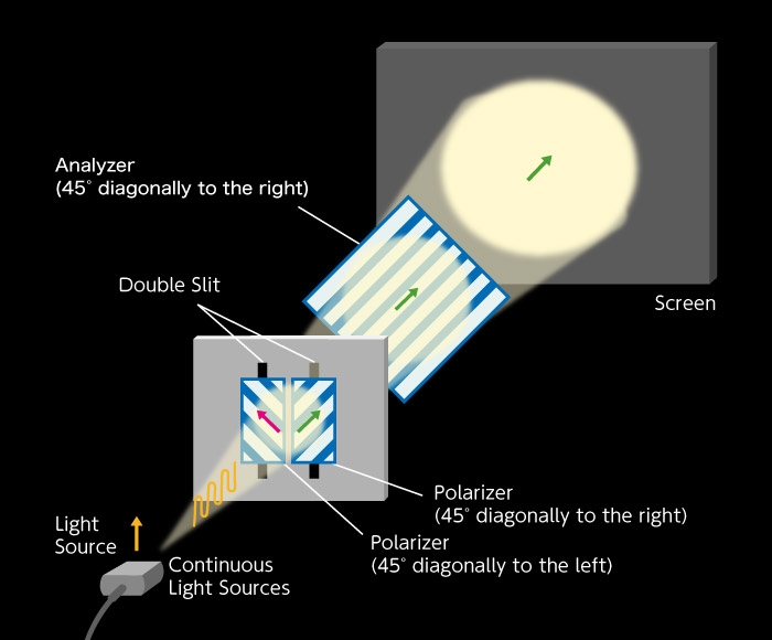
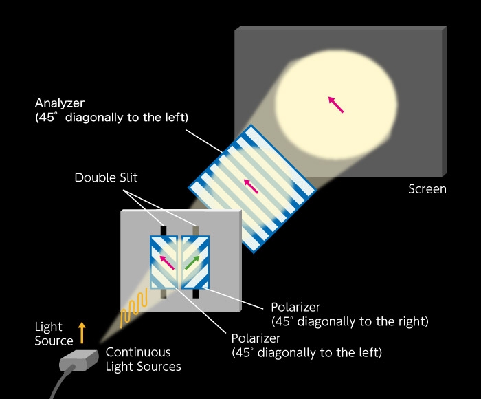
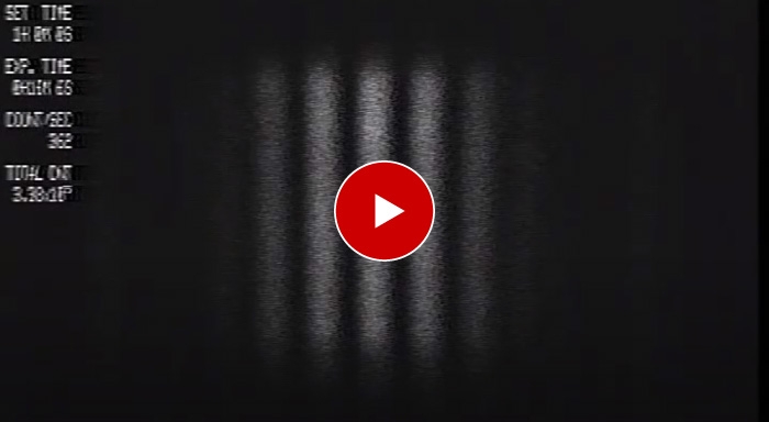
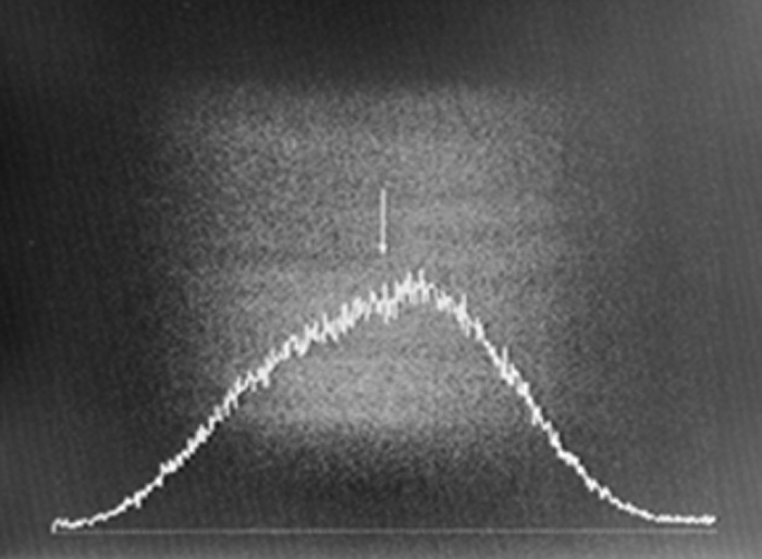
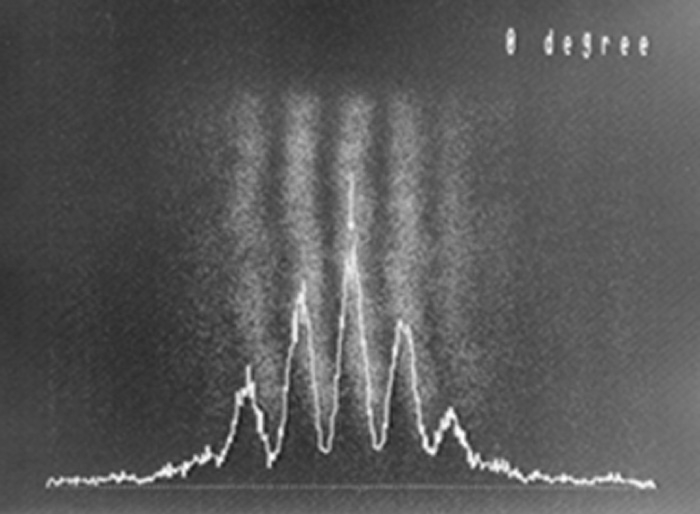
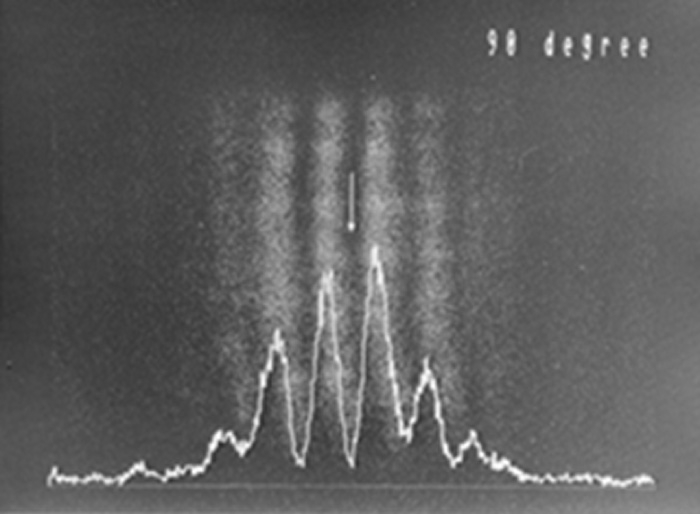
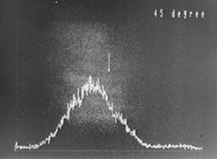
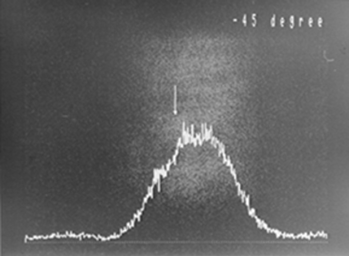
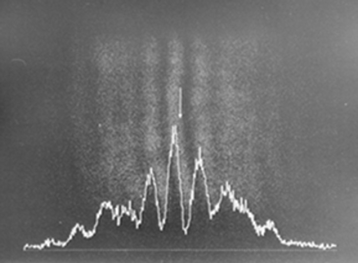
As we saw in Figure B-6, two polarized lights crossing at a right angle do not interfere with each other, so there are no interference fringes occur in Figure E-1. The light from both slits is observed, and appears to spread both left and right. In Figure E-2, interference fringes can be seen just like in Young's interference experiment (Video 2). In Figure E-3, dark and bright light positions are opposite of those in Figure E-2. In Figure E-4, only the light from the slit on the right is transmitted, so it is biased to the left (left and right appear inverted in cameras). In Figure E-5, the pattern is the opposite of Figure E-4. In the final experiment, the normal Fresnel / Arago polarization interference experiment was expanded upon to use circularly polarized light. Specifically, a quarter wavelength plate was added in front of the double slit. Results of this experiment are shown in Figure E-6. In this state, there is a quarter wavelength phase shift in the polarized light components that pass through each of the double slits. The phase shift moved the interference fringes laterally by a quarter wavelength, and the center of the screen is located in the midpoint of the bright and dark parts of the interference fringes.
Figure D: Fresnel Arago polarization interference experiment in short pulse single photon state
Figure E-1: When there is no analyzer, interference fringes do not appear
Figure E-2: When the analyzer is in the vertical direction, interference fringes appear
Figure E-3: When the analyzer is in the horizontal direction, interference fringes appear (bright and dark positions are the opposite of Figure E-2).
Figure E-4: When the analyzer is tilted diagonally 45° to the right. No interference fringes appear.
Figure E-5: When the analyzer is tilted diagonally 45° to the left. No interference fringes appear.
Figure E-6: When the incident light to the double slit is circularly polarized. The center of the screen is just in the midpoint of the bright and dark parts of the interference fringes.
Video 2: “Fresnel & Arago Polarization Interference Experiment in Short Pulse Single Photon State” (Hamamatsu Photonics, 1990)

Please refer to this page (Copyrights and trademarks) in order to use or quote the images and video content on this page for other media.


See these references on "Young's Interference Experiment with a Single Photon Using Short Light Pulses" and ”Fresnel / Arago polarization interference experiment in a short pulse single photon state”.

Reference (1)
H. Takahashi, S. Aoshima, T. Urakami, T. Takemori, I. Hirano, and Y. Tsuchiya, Young's Interference Experiment in the Single-Photon Region Using Short Optical Pulses, Kogaku, 20 (1991) 108-111. [published in Japanese]

https://annex.jsap.or.jp/photonics/kogaku/public/20-02-kenkyu6.pdf


Reference (2)
H. Takahashi, S. Aoshima, T. Urakami, T. Takemori, I. Hirano, and Y. Tsuchiya, Interference Experiment of Polarized Light in the Single-Photon Region, Kogaku, 21 (1992) 165-168. [published in Japanese]

https://annex.jsap.or.jp/photonics/kogaku/public/21-03-kenkyu.pdf

The mystery remains… When are the properties of photons determined?

In this experiment, some things seem mysterious indeed. In Young's interference experiment, a single photon was observed passing through two slits at the same time and appearing as a particle on the screen, resulting in interference fringes that show its nature as a wave. In the Fresnel & Arago interference experiment, a polarized photon that has passed through the two slits appears as “transverse waves” 45˚ diagonal to the right and 45˚ diagonal to the left. Consider this: what are the implications of the fact that a single photon can show states of two perpendicular polarized lights at the same time? And what happens after it passes through the analyzer?

They discovered one of the true natures of light, which is that light is a “transverse wave”. Simultaneously, through more advanced experiments using “polarized light”, they found that a photon exhibits even more mysterious behavior. For all of us seeking to find the true nature of photons, this invites us to look ever deeper into the mysteries of light. In 1917, Albert Einstein said, “For the rest of my life, I will reflect on what light is.” Likewise, light continues to motivate us to take on new challenges.

[supervisor]
Mr. TAKAHASHI